 Add Column ( Modeling > F2 >
  Structural Steel > select " Column ")
Tool summary :
- Adds a column to the 3D model. In a plan view, locate a single point, then set the column's top and bottom elevations on its edit window.
- You can also add a column by locating two points in an elevation view. The box for " Sloped column " is checked automatically if you add (or repeat) a column whose two work points are not aligned vertically. The two work points of a column define the neutral axis of the column's main material.
- Another way to add a column is to use Repeat . For a column whose settings you want to duplicate, double-click the column and press " OK " on its edit window without changing anything. Then invoke Add Column and middle-click ( Repeat ) to lay out a new column like the double-clicked one. Be aware that Repeat also sets the end elevations to exactly match those of the original column if User and Site Options > Modeling > " Classic column location " is checked.
- See (on this page):
Also see :
- Modeling (where Add Column is a tool)
- Column (index)
- Column Edit window (opens with Add Column unless you show the options bar)
- Show member add options bar ( User and Site Options > Modeling > ) (
 )
)
- Automatically process after modeling operation ( User and Site Options > Modeling > )
- Member component items to copy/repeat ( User and Site Options > Site >, affects Repeat )
- Member status items to copy/repeat ( User and Site Options > Site >, affects Repeat )
- Classic column location for columns ( User and Site Options > Modeling > ) ( ) .
- How left end relates to work point coordinates (topic)
- Member Copy (alternative to Add Column )
- Erase Member (to undo Add Column )
- Edit Member (various ways to edit a column)
- Select a column, right-click (Menu) , choose " Edit " (one way to edit a column)
- "Edit Other" to edit all members under one mark (highly recommended)
- Move/Stretch Members (to move or stretch columns)
- Move/Stretch Members Include Material (same as Move/Stretch , but often better)
- Constructing the 3D Model (topic)
page 1 | contents | F2 > structural steel > column | top
Videos :
|
|
page 1 | contents | F2 > structural steel > column | top
Quick instructions (also see the videos and the detailed instructions ) :
|
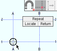
1 . Invoke Add Column , then left-click ( Locate ) when the target ( |
|
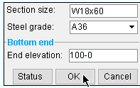
2 . On the Column Edit window, enter the settings for the column, including its top and bottom " End elevation ." |
|
3 . The new column appears on your computer screen. Right-click ( Return ) if you are done adding columns. Or you can left-click ( Locate ) or middle-click ( Repeat ) if you want to add another column. |
page 1 | contents | F2 > structural steel > column | top
Detailed instructions (also see the quick instructions ) :
Add Column can be used to add columns to the 3D model of your current Job. The following instructions assume that you are using a 3-button mouse.
1 . Before adding a column:
1a : Check (
) the box for User and Site Options > Modeling > " Classic column location for columns added/repeated in plan view " to your preference. The option affects the default entry to the top/bottom " End elevation " for columns added/repeated in a plan view.
1b : Open a plan view at an elevation through which the to-be-added column(s) will pass. Alternative: You can optionally add columns by locating two points in an elevation view. In a plan view, you only need to locate one point.
1c : Lay out grid lines or construction lines so that there are points of intersection ( INCL points) where you want to place the centers of the columns.
1d : Optionally set the toolbar icon or set User and Site Options > Modeling > " Automatically process after modeling operation " to a choice that will cause the column you are adding to automatically have solids created and piecemarks applied when you press " OK " to close the Column Edit window that opens in step 4.
2 . Invoke Add Column using any one (1) of the following methods:
- Right-click ( Menu ) and choose Add Member > Structural Steel > Column .
- On your ribbon, click the Add Column icon. If the icon is not currently on the ribbon, you can add it using the Ribbon Editor . In the Ribbon Editor , choose Model -- Member > Add Column .
- Use a keyboard shortcut (for example, F2 ). Add Column is in the keyboard configuration " Command group " called ' Model -- Member '.
- With Member Mode mouse bindings active, middle-click ( Add ). On the selection dialog that opens, double-click " Column. "
- You can also add the tool to a mode of your choice. In Mode Configuration , the tool can be selected from the " Command group " called ' Model -- Member '.
3 . Various Locators become active along with Locate - Repeat - Return mouse bindings .
|
|
|
bindings |
3a : Select the Locate icon you want (if it's not selected already), then move the mouse pointer (
) so that the point location target (
) snaps to where you want the work line of the column, then left-click ( Locate ).
3b ( a special case ): If you are in a plan view , go to step 4. If you are in an elevation view , left-click ( Locate ) when the point location target (
Note: Column worklines (stick form member lines) are drawn through the neutral axis of a wide flange , S shape , welded plate wide flange , welded plate box , HSS round or HSS rectangular column.
4 . The Column Edit window opens. On it are settings for the column whose work point(s) you defined in step 2. Since process on the fly takes place even before the window opens, all relevant connection design locks are available to you immediately after the window opens, and process on the fly will continuously update connection design locks as you make changes on the edit window.
Alternative 1 : Edit the settings as desired (see the notes below), then press the " OK " button. Go to step 5.
Alternative 2 : Press the " Cancel " button to close this window and go back to step 3.
Note 1: The default settings on this window are those of the last column added or edited in this session of Modeling . Even if all you do is double-click a column and press " OK " on its edit window, that column's settings become the defaults for the next-added column. You therefore only have to make changes to those settings which are different for this column.
Note 2: If you located the column in a plan view (using a single work point), it is especially important that you enter the correct " End elevation " for the top end and bottom end of the column. For columns other than the first-added column, the choice made to User and Site Options > Modeling > " Classic column location for columns added/repeated in plan view " indirectly affects the top/bottom " End elevation " values that are entered.
Note 3: Certain column settings pertain to the physical geometry of the column. For instance, " Column rotation " and " Section size ." These must be set properly in order for you to get the connections you want on this column and on members that frame to this column.
Note 4: Connections can be designed to a sloping column as well as to a perfectly vertical column. Click here , here , here or here for examples. Click here or here for examples examples of base/cap plates on sloping columns.
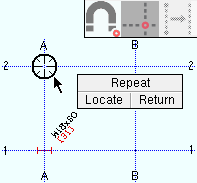
5 . The column is shown in stick form on screen (as a cross-section if you are in a plan view). Locate - Repeat - Return mouse bindings become active. If User and Site Options > Modeling > " Automatically process after modeling operation " is set to ' Process and create solids ', the new column will have automatically undergone all phases of Process and Create Solids . If that User and Site Option is ' Process ' or ' Do nothing ', you will have to Process > Process and Create Solids in order to have the member piecemarked and able to be displayed in a solid form . Do one (1) of the following:
|
|
|
bindings |
Alternative 1 : Move the mouse pointer (
Alternative 2 : Repeat this procedure beginning with step 3 to add a column that is slightly different than the one you just added.
Alternative 3 : Right-click ( Return ) if you are done adding columns.
page 1 | contents | F2 > structural steel > column | top
Adding columns using the options bar (classic) :
|
|
User and Site Options > Modeling > " Show member add options bar " can be set to ' Disabled ' or ' Top ' or ' Bottom '. When ' Top ' or ' Bottom ' is selected, extra space is allocated on your top or bottom toolbar to provide feedback and options related to the adding of a beam, column or brace. When you choose Model > Member > Add > Column or invoke Add Column using any other method , the options bar is activated, allowing you to quickly add columns without having to open the Column Edit window. Note in the following example that the bottom " End elevation " and top " End elevation " are locked ( ![]() ), which results in the elevation of the member ends being determined by the entered values. Also, the entry made to " User defined connection " is valid due to the " Input connection type " being set to ' User defined '.
), which results in the elevation of the member ends being determined by the entered values. Also, the entry made to " User defined connection " is valid due to the " Input connection type " being set to ' User defined '.
![]()
The " Launch member edit " button (
or
) stops and starts the opening of the Column Edit window with each column that is added. The normal default that is applied to the first member added in a Modeling session is to not open the member's edit window. If you want the window to open, click the icon before you locate a point to add a column. The window opens for each column that is subsequently added during your current Modeling session until you click the icon again or restart Modeling .
The " Continuous add mode " button (
or
) is visible -- and therefore, usable -- only when you are in an elevation view . It stops and starts continuous mode. Columns added using continuous mode are end-to-end, with the second point of a just-added column the same the first point of the next-added column. This makes continuous mode useful for adding spliced columns. Continuous mode requires the location of fewer points than the two clicks (one for each end) that are required for adding a column in an elevation view in non-continuous mode. You need to turn continuous mode off before you can add a column that is not end-to-end with the previously added column.